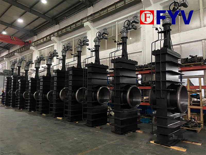
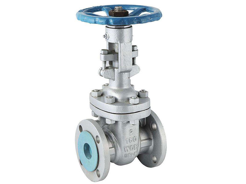
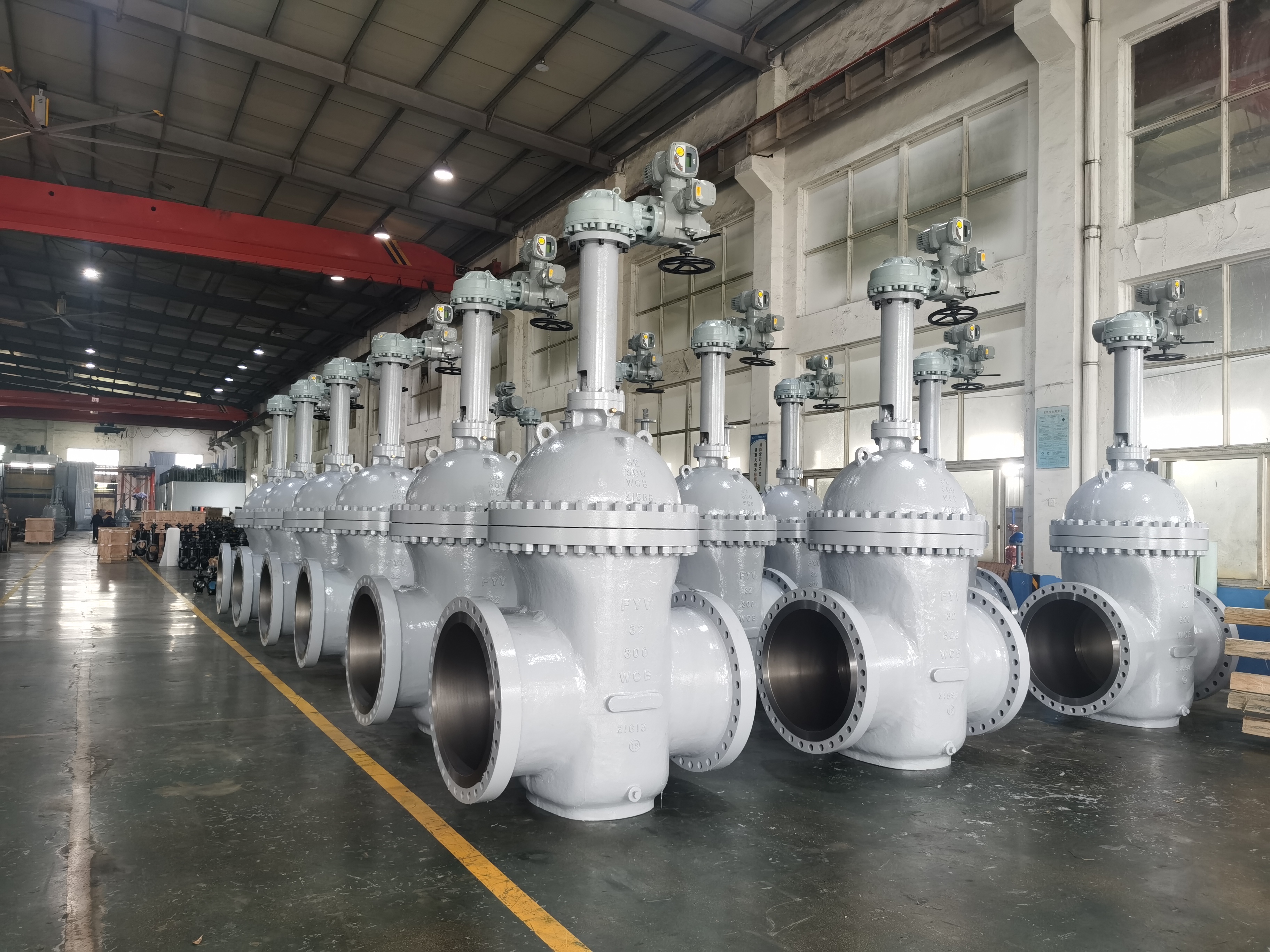
API 600 Wedge Gate Valve
The API 600 wedge gate valve follows the American Petroleum Institute specification 600 for steel gate valves in petroleum and natural gas service. These valves handle high-pressure and high-temperature conditions with a solid or flexible wedge that presses firmly against the seats to deliver tight shut-off.
Drive Devices
The drive device moves the valve stem to raise or lower the gate. Common options suit different needs:
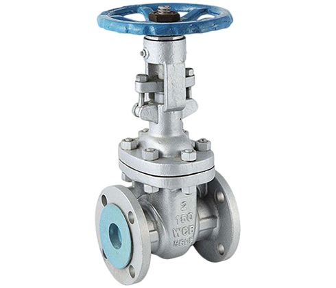
- Manual handwheel setups, either gear-operated or direct, work well for smaller valves or infrequent use. The handwheel turns a threaded stem that shifts the gate up or down.
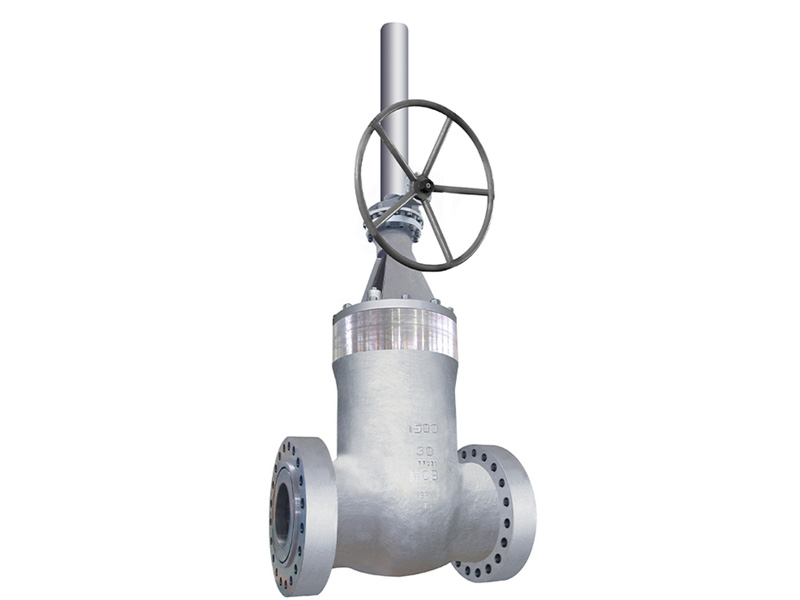
- Bevel gear operators fit larger valves or spots that need extra torque. The gearbox cuts the effort required and gives smoother control.
- Electric actuators appear in automated plants. An electric motor drives the stem, with built-in torque and position limits for accurate remote operation.
- Pneumatic and hydraulic actuators see less use because of space and stroke needs, yet they serve where quick or powerful action matters.
Stem Configurations
The stem can rise or stay non-rising. Rising stems show the valve position at a glance. Non-rising stems save space in tight installations. The chosen drive device must match torque demands, cycle frequency, and site conditions to keep the valve safe and reliable throughout its service life.
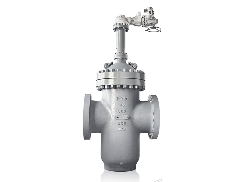
Water Seal Gate Valve
The water seal gate valve serves high-temperature gas systems such as flue gas lines in power plants and industrial furnaces. It stops gas leaks, especially with hot or hazardous gases, by adding a water barrier instead of depending only on metal or resilient seals.
Operating Principle
The valve combines a standard gate mechanism with a water sealing chamber in the body. When closed, the gate blocks the flow path. At the same time, a water reservoir above the gate or around the chamber creates a continuous liquid barrier along the gate edges and bonnet area.
This water layer fills micro-gaps that metal parts cannot seal alone. It adjusts to pressure swings and thermal expansion, cutting leak paths that ordinary seals might miss under heat or cycling.
A steady water supply, fed by pumps or gravity tanks, keeps the chamber full. Overflow drains, level gauges, and temperature safeguards maintain proper operation.
Materials and Applications
Manual or electric actuators control gate movement. Internal parts use stainless steel or special linings to fight corrosion, scaling, and high heat. The design fits systems that demand total gas tightness where conventional seals break down from temperature or chemicals. The water barrier adds a dependable extra layer that improves safety and meets environmental rules.


 English
  русский
  Español
  عربى
عربى