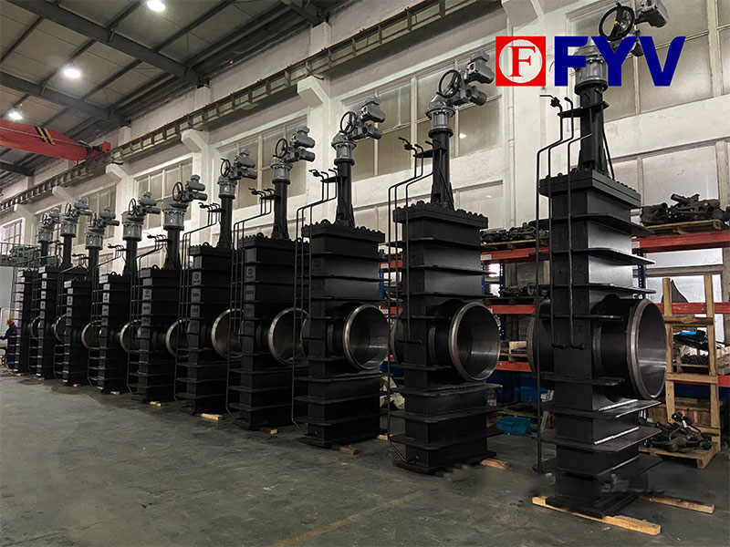
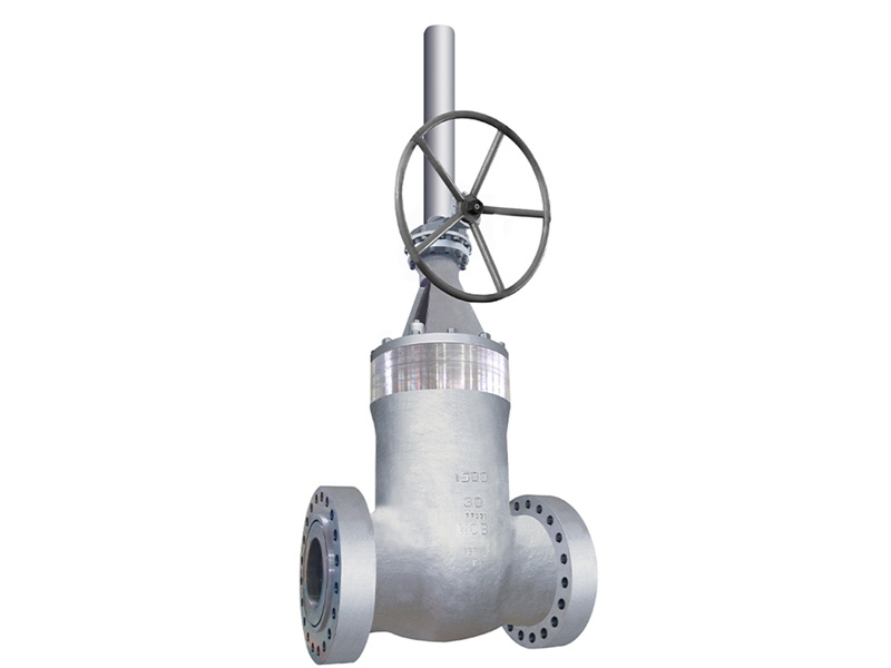
High-pressure sealing gate valves are critical fluid control devices designed for demanding conditions (e.g., high pressure, high temperature, or corrosive media). Their core function relies on specialized designs to achieve reliable sealing. Below is a detailed breakdown of their working principle.
1. Basic Structure
-
Valve Body
-
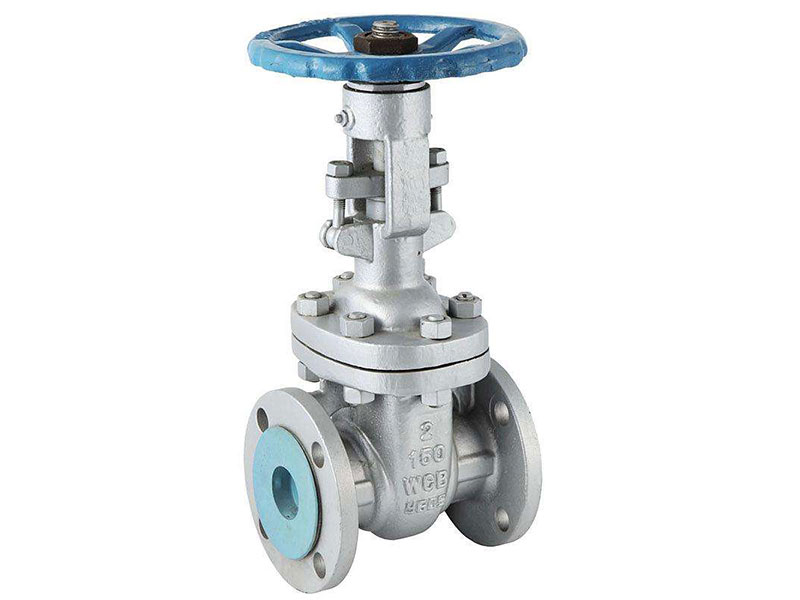
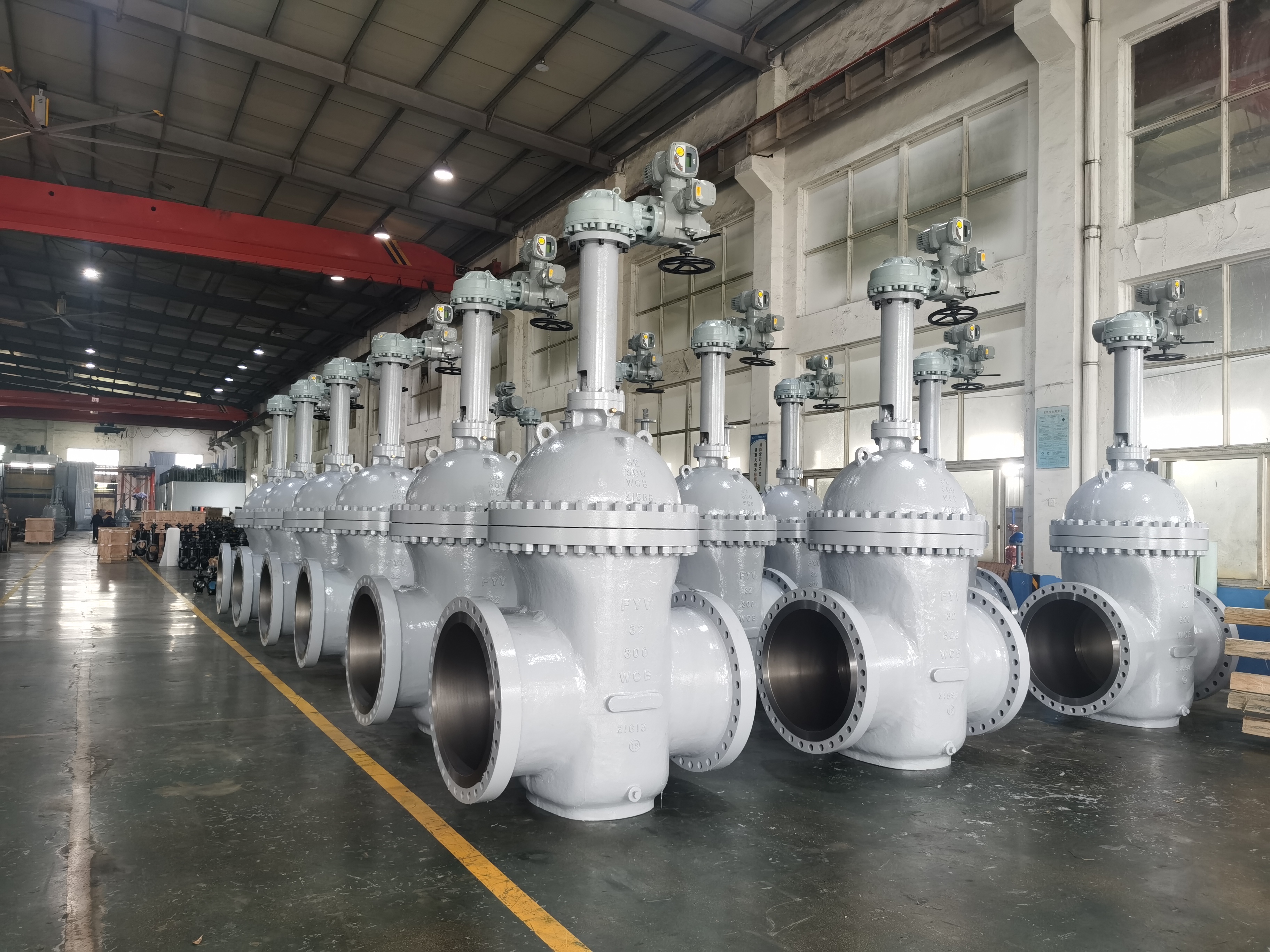
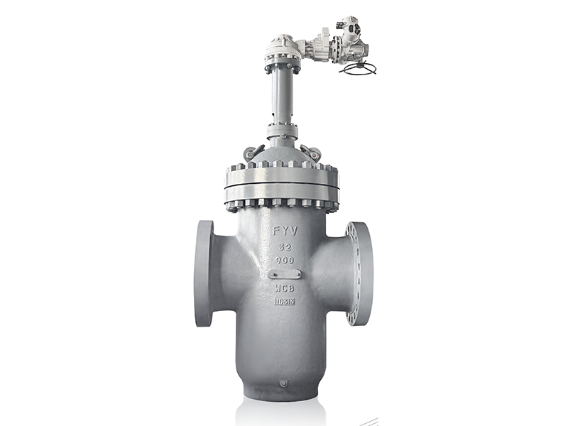
The pressure-bearing component, typically made of forged steel (e.g., A105) or alloy steel (WC6), featuring a full-bore design to minimize pressure drop.
-
Gate (Disc)
-
Solid Wedge: Cast as a single piece for stable performance in high-pressure applications (e.g., Class 600 and above).
-
Flexible Wedge: Incorporates springs or hinges to adapt to minor seat deformation, improving sealing.
-
Valve Seat
-
Stem
-
Stem Packing System
2. Sealing Mechanism
(1) Bidirectional Sealing
(2) Pressure-Enhanced Sealing
-
Under high pressure, media forces the gate tighter against the seat (e.g., wedge gate valves), creating a pressure-assisted seal where sealing force increases with system pressure.
(3) Critical Sealing Points
-
Gate-to-Seat Interface: The primary sealing surface, resistant to erosion and particle wear.
-
Stem Packing Seal: Pre-compressed packing prevents leakage along the stem.
-
Body-to-Bonnet Seal: Uses spiral-wound gaskets or ring-joint gaskets.
3. High-Pressure Adaptations
-
Reinforced Structure
-
Fire-Safe Design (API 607/6FA)
-
Blowout-Proof Stem
4. Typical Operation Sequence
-
Opening Process
-
Closing Process
-
Sealing Tests
5. Key Selection Considerations
-
Extreme Conditions: For ultra-high pressure (≥Class 2500), choose parallel slide or double-disc gate valves.
-
Corrosive Media: Apply WC or CrC coatings on seats for extended service life.
-
Actuation Method: High-pressure valves should use electric/hydraulic actuators (e.g., thrust ≥10kN).
Conclusion
High-pressure sealing gate valves achieve reliable shutoff via precision metal sealing, pressure-assisted enhancement, and reinforced construction. Selection must account for pressure class, media properties, and safety standards (e.g., API 6D), with regular maintenance of sealing systems ensuring long-term performance.


 English
  русский
  Español
  عربى
عربى