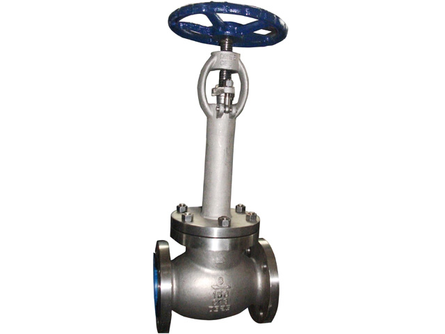
The Cryogenic Globe Valve is specifically engineered to function reliably at low temperatures, often in applications involving liquefied natural gas (LNG), liquid nitrogen, and other cryogenic fluids. Welding is a critical process in its production, contributing directly to the valve's structural integrity, leak-tightness, and performance under thermal stress.
Key Requirements and Preparation
The welding process begins with the selection of suitable materials, typically stainless steels or high-nickel alloys, which are chosen for their strength and toughness at cryogenic temperatures. Prior to welding, components are carefully cleaned to remove contaminants such as oil, moisture, or oxides, as even small impurities can bring about poor weld quality or cracking at low temperatures.
Welding Techniques and Execution
Gas Tungsten Arc Welding (GTAW), also known as TIG welding, is the commonly used technique due to its precision and ability to produce clean, high-quality welds. The process is typically performed in controlled environments to maintain temperature and shield gases such as argon are used to protect the weld pool from oxidation.
Multiple passes are applied depending on the thickness of the material. Each pass is followed by thorough inspection, often using non-destructive testing methods like dye penetrant or ultrasonic testing, to ensure weld integrity. Post-weld heat treatment may be omitted for certain cryogenic alloys, but stress-relieving can be performed if specified.
Final Considerations
The welded joints of a cryogenic globe valve must exhibit high resistance to thermal cycling and ensure absolute tightness. Therefore, welding personnel are required to be qualified under stringent welding procedure specifications (WPS), and the entire process is closely monitored. The result is a structurally sound valve that performs reliably in critical cryogenic applications.
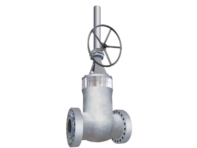
The Double Disc Check Valve, also known as a dual plate check valve, is designed to prevent backflow in piping systems by using two spring-loaded discs that close quickly when flow reverses. Its design reduces pressure drop and allows for installation in horizontal or vertical pipelines. The production process of this valve involves several precise manufacturing stages to ensure functionality, durability, and compliance with industry standards.
Material Selection and Casting
Production begins with the selection of appropriate materials such as stainless steel, carbon steel, or other alloys, based on the intended application. The valve body is usually manufactured through sand or investment casting, with the goal of achieving uniform wall thickness and dimensional accuracy. Post-casting, the body undergoes heat treatment to improve mechanical properties and stress distribution.
Machining and Assembly
Precision machining is employed to create internal surfaces, guide slots, and seat areas. CNC machines are commonly used for this stage to maintain tight tolerances and ensure proper alignment between the discs and seating surfaces. Each disc is then machined and fitted with torsion springs, allowing for immediate closure during flow reversal.
The hinge mechanism, a crucial element in the valve's operation, is assembled with emphasis on friction and wear. The seating surfaces are lapped to achieve a tight seal, and the valve's internal components are balanced to avoid vibration during high-flow operation.
Testing and Finishing
Each Double Disc Check Valve is tested under hydrostatic and air pressure conditions to validate its sealing performance and structural integrity. Functional testing under simulated flow conditions is also performed to ensure the discs close rapidly and uniformly.


 English
  русский
  Español
  عربى
عربى